- IC matching information (move to another page)
- Types of crystal cut
- Crystal unit equivalent circuit
- Frequency-temperature characteristics
- Test Circuit
- Output wave-form
Types of crystal cut
Relation among crystal cut, mode of vibration and frequency range
| Crystal Cut | Mode of vibration | Frequency range (kHz) | Capacitance ratio (C0/C1) |
|
|---|---|---|---|---|
| AT | Thickness shear Fundamental |  |
800~5,000 2,000~80,000 |
450~300 220 |
| 3rd overtone |  |
20,000~90,000 | n2 x 250 n: Overtone order |
|
| 5rd overtone | 40,000~150,000 | |||
| 7rd overtone | 70,000~210,000 | |||
| BT | Thickness shear Fundamental | Thickness shear Fundamental | 3,000~30,000 | 650 |
| XY | Flexural (Tuning fork) |  |
16~150 | 425~800 |
| Extensional | 600~3,000 | 400 | ||
| DT | Face shear |  |
100~500 | 400 |
| CT | 150~850 | 350 | ||
| SL | 180~700 | 400 | ||
Crystal unit equivalent circuit
A crystal unit in the main resonance frequency may be expressed as an electrical equivalent circuit: a circuit ordinarily composed of a series circuit consisting of an inductance, capacitance and resistance, and a capacitance connected in parallel to the series circuit as shown in the drawing.
Here, C0, which is commonly known as the shunt capacitance, comprises an inter-electrode static capacitance to which the inter-terminal stray capacitance is added.
L1 and C1 are the equivalent constants of the crystal unit viewed as an electrical and mechanical oscillation system. Since both constants are determined by such factors as the type of cut, cutting angle, dimensions of the crystal blank, and construction of the electrodes, and are thus reproducible, crystal units can be manufactured with high precision.
R1, which denotes oscillation loss, is governed by conditions such as processing, storage, and dimensions of the crystal unit.
L1 is referred to as motional inductance, C1 is referred as motional capacitance, and R1 is referred as motional (series) resistance.
| L1 | Motional inductance |
|---|---|
| C1 | Motional capacitance |
| R1 | Motional(series)resistance |
| C0 | Shunt capacitance |
The electrical equivalent circuit, composed of L1, C1, R1 and C0, all of which are correlated, may be expressed by the following equation.
Shown below are some equations by which the performances of crystal units are expressed.
Frequency-temperature characteristics
Correlation between Crystal cutting angle and Frequency-temperature characteristics
Frequency-temperature characteristics of Tuning Fork Crystal Unit
Correlation between Crystal cutting angle and Frequency-temperature characteristics of AT-cut Crystal Unit
Test Circuit
CSX-750F SERIES
*1
| 390Ω | CSX-750(FC) |
|---|
CMOS load
*2
| 50pF | CSX-750(FC) |
|---|---|
| 30pF | CSX-750(FB, FJ) |
| 15pF | CSX-252F |
Current Consumption
Output wave-form
Oscillators output wave-form
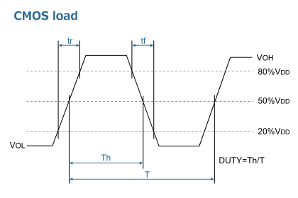
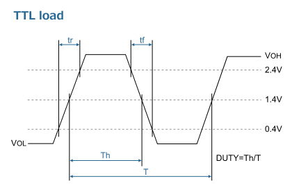
Measurement conditions
- Oscilloscope・Input impedance: No less than 1 MΩ・Input capacitance: No more than 15 pF・Band width: No less than 500 MHz・Make the grounding lead of the probe as short as possible.
- The CL includes the probe capacitance.
- Grounding should be single-point grounding.
- Supply voltage impedance should be as low as possible. Rise time from 0V to 0.9Vdd is to be more than 150 μs.
- Use an ammeter with small internal impedance.